Navigating the High-Frequency Highway: A Signal's Journey Across the PCB Landscape 🌐⚡️
Have you ever wondered why your carefully designed PCB sometimes behaves unpredictably at high frequencies? 🤔
✨ Imagine YOU Are the Signal ✨
Imagine you're a high-frequency signal born from a bustling IC city. Your mission is to travel across the PCB to deliver critical data to a distant chip village 🦸🏽♀️
🌉 The Challenge of Long Bridges (Traces)
As you race along the copper trace highway, you realise it's no ordinary road. It's a transmission line, resonating with your high-speed energy ⚡️ In the world of GHz, you’re more than just electricity; you’re a wave of electromagnetic energy, and every inch of the trace matters! 📏
🔊 Echoes in the Line (Reflections)
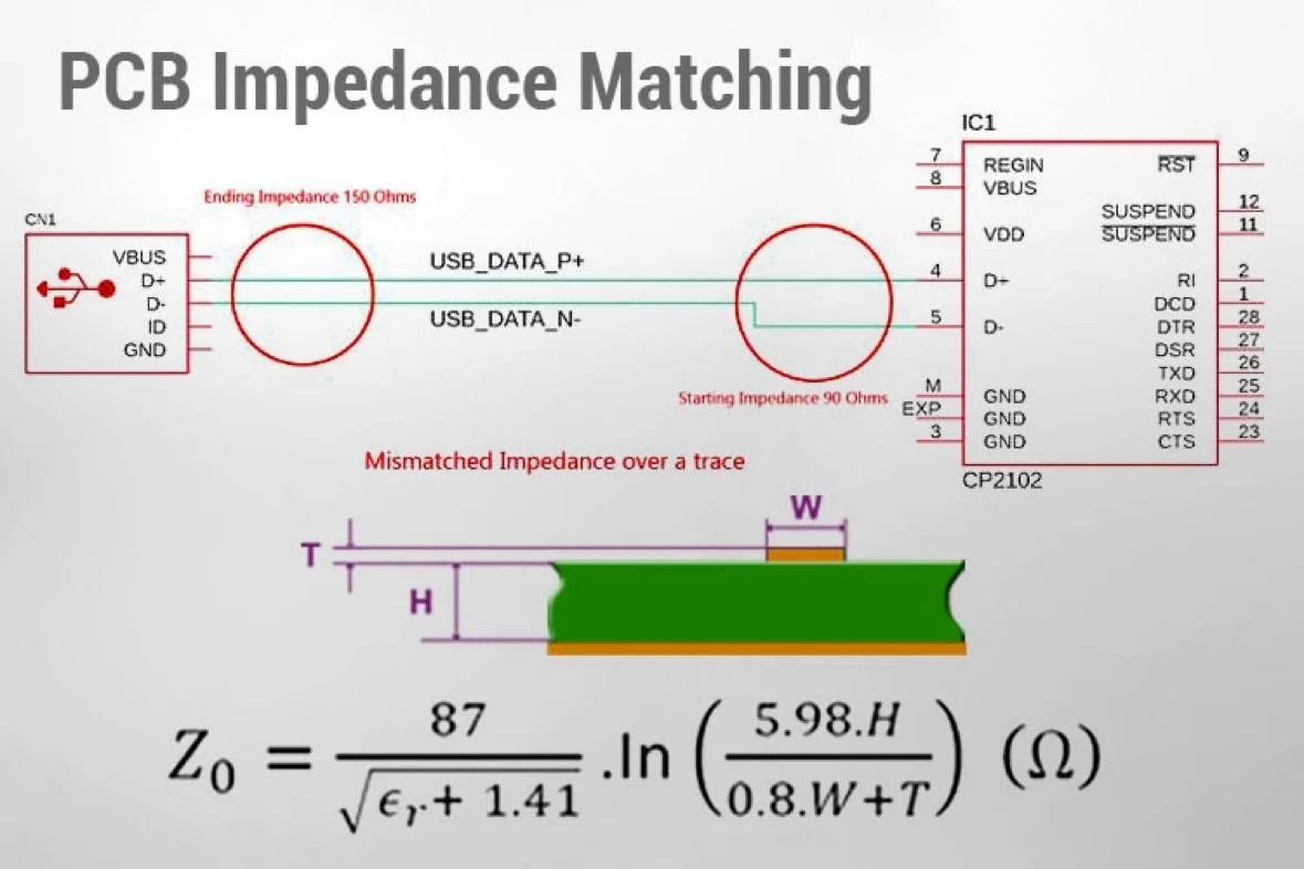
Suddenly, you hit a mismatched impedance junction, and part of your energy bounces back! 😱 like shouting in a canyon and hearing your own echo – except these echoes can mix with incoming signals, creating a LOT of confusion 😩
🔧 Impedance Matching and Termination
But fear not! A well-placed impedance matching hero steps in, aligning with the trace's characteristic impedance 🙌🏽 It’s a perfectly tuned bridge that allows you to cross without sending ripples back. This smooths your path, ensuring your message arrives intact and on time ⌚️
❄️ DEFINITIONZzZz ❄️
🌟 Characteristic Impedance (Z0) is a key property of transmission lines, representing the impedance that completely absorbs the signal with no reflections.
🌟 Reflections are a mismatch in impedance which cause reflections. Proper termination is necessary to avoid these reflections 🪞
❄️ LESSONS ❄️
👉🏽 When a PCB trace carries high-frequency signals, it can start to emit some of that signal energy into the surrounding environment, just like an antenna would.
👉🏽 This can lead to electromagnetic interference (EMI), affecting other electronic components or systems nearby. It can also result in the loss of signal power from the trace itself‼️
👉🏽 The effect becomes more pronounced when the length of the trace is close to a significant fraction (like 1/4th or 1/2) of the signal's wavelength. At these lengths, the trace can efficiently convert the signal into radiated electromagnetic waves.
👉🏽 A transmission line impedance is determined by the physical properties of the trace (like its width, thickness, and the PCB material). If the source, trace, and load impedances aren't matched, part of the signal will reflect back toward the source, leading to signal degradation.
So, basically, when dealing with lower frequencies, you can think of a PCB trace as just a regular wire 🤷🏽♀️ But when the frequencies get higher, the trace starts to act differently. It’s not just a wire anymore – now, things like its own tiny built-in resistance, and its ability to store and release energy (capacitance and inductance), really start to change the way the signal moves along it! ⚡️⚡️