How Can the ADP3450 Be Used for Wireless Charging Development?
COILS COILS COILS

If you’re like me, you’ll have many wireless charging coils around your lab for various standards. They likely entered your lab well-dressed; adorned in well-labelled packaging, which told you exactly the value of its inductance, resistance, and current rating. But, perhaps, the coils were having a lot of fun in the lab, and the well-labelled packaging that was once their home is now nowhere to be found.
Or, perhaps, it’s another glorious day in your lab; you have lots of ideas and are ready to do some prototyping. But the next-day delivery just isn’t quick enough when you need to prototype now. The only thing you can prototype some wireless charging with right now is some enameled wire you’ve been using for your PCB re-work.

How will you determine the coil inductance for your unlabeled coils or your DIY enameled hack? You, my friend, may be looking for an LCR metre. Or are you?
Some LCR metres struggle with detecting millihenries, let alone microhenries. Having the right one can be an investment. Don’t get me wrong, an LCR metre is a piece of equipment that nobody would complain about having in their lab. Being stuck with this problem without an LCR metre can mean that calculating the receiver coil inductance becomes a complicated process requiring multiple pieces of equipment like an oscilloscope and a separate signal generator. But what if you have an ADP3450?
EQUIPMENT LIST
2 x BNC scope probes OR 1 x BNC scope probe and 1 x BNC minigrabber (check probe bandwidth)
A resistor of a known resistance
WaveForms software
All your stray coils
STEPS

1. In your new WaveForms workspace, open a new wavegenerator window.

2. Generate a 1kHz sine wave with a 1.5V amplitude.

Make it stand out
3. Connect your probe or BNC minigrabber to Channel 1 of the “wavegen out” section on your ADP3450, and a probe on the first channel of the oscilloscope section.
4. Open a new oscilloscope window. Connect your generator to your oscilloscope then make sure both the wave generator and the oscilloscope are running.
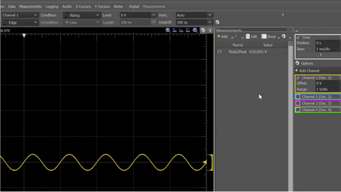
5. Click measurements on the Oscilloscope, and add Peak2Peak. You should now see a peak to peak voltage of 3V.

6. Find a through hole resistor with a known value. If you have a multimeter with a resistance measurement capability handy, feel free to measure your resistor to get a more accurate reading.

7. Connect the resistor between the ground clips and the probe tips of your oscilloscope and wave generator. You have now created a voltage divider with the resistance of the ADP3450 along with the probes on one side, and your known resistor on the other side.

8. Observe the new peak to peak voltage on the oscilloscope and make a note of it. Mine was 0.65V.
9. Calculate the internal impedance by using a regular voltage divider equation:
R1 = R2 x ((V1/V2)-1)
In this case: R2 = 100.2R, V1 = 3V, and V2 = 0.65V
So R2 = 400R

10. Replace the resistor with one of your stray coils (Tip: run your soldering iron on the tips of the coils to burn more of the thin layer of insulation so you can have more conductive surface area for probe contacts).

11. Observe the change on the oscilloscope. Most wireless charging coils will have an inductance value in microhenries, so you should see the voltage drop to millivolts.

12. On the signal generator, increase the frequency until the peak to peak voltage on the oscilloscope is half the original input. So, if the original input was 3V peak to peak, find the frequency where the peak to peak is 1.5V. I found mine at 3.51Mhz. (Tip: the ADP3450 along with WaveForms software allows you to write nifty scripts. Could you automate this step with a script that finds the right frequency automatically?)

BUT WHY?
Why does this work? How does this work?
When the inductor is connected to the generator, current passes through it. This means that there’s now a voltage drop across the internal impedance of the equipment, which we calculated in step 9. This voltage drop can be seen on the oscilloscope in step 10.
When voltage seen at the scope is half that of the wave generator, we can solve this algebraically by:
VScope/VGen = 1/2
Because voltage is a function of frequency and inductance, we can deduce the inductance with a known frequency and voltage. So, at the scope, VScope = I x 2πf1L, and at VGen = I x (2πfL + R)? Sort of. But, not really. When we are dealing with inductance, we are dealing with complex impedance and imaginary numbers, so a more accurate equation would be:
VScope/VGen = 2πf1L / Square Root of((2πfL)^2 + R^2) = 1/2
Solving for this equation gives L^2 = R^2 / (3 x (2πf)^2), which results in the familiar equation we used in step 12:
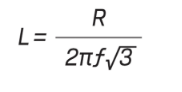
NOW WHAT?
Now you have the inductance of the coil, you can assess if it is suitable for, say, Qi charging and calculate resonant capacitors needed for a properly tuned circuit. Speaking of tuning, can the ADP3450 help us with selection of the wider resonant circuit? That’s next, stay tuned! (pun unintended)